 |
Servos, Receiver and Battery:
Now that the airframe is done it's time to start installing the electronics. The servos come pre-installed, but I opted to turn the elevator and rudder servos around so the horns were towards the aft of the plane and as far away from the battery as possible. This insures the battery wont interfere with their motion.
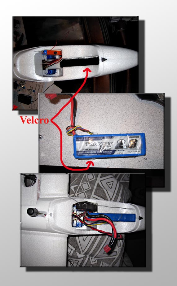
Next I installed a 1/2 inch strip of velcro on the inside bottom of the nose and along the long edge of the battery (see pics). This will do a nice job of holding the battery in place during flight. I've been running a Turnigy 3 cell 2650 mAh battery that weighs in at 7.8oz. If the battery is installed as far forward in the nose as possible the CG will be perfect without having to install any ballast. I'm also using deans connectors on the battery and speed controller connections.
The receiver goes in next. I've had several receivers installed at variouse times and they have all fit on the side of the cockpit area angled back slightly to allow the the canopy to fit. It may require cuttinr away a little foam along the side depending on the receiver. Currently I'm using a Corona V2 2.4 GHz system which has been working great. A nice bonus is it coexists nicly with the 2.4GHz XBee telemetry system I'm using. I've seen no interference problems whatsoever. I drill a small hole in the canopy to allow one of the antennas to pock thru and extend in a vertical direction. The other arial slips under the canopy and along the lead edge of the wing to cover the horizontal orientation. You'll most likley need to pre-install the servo connector first before installing the receiver into the plane as the connectors may exit out the bottom of the receiver. This gives the cleanest installation as it will allow the wires to run along the bottom and into our autopilot compartment without interfearing with the servos. I'm using five channels -> Elevator, Rudder, Throttle, Aileron and an autopilot enable channel. To keep the wires neat and tidy I use some lacing material to tie them up. Just make sure you've labeled them somehow so you know where to plug them in to the autopilot.
|
|
Autopilot and Speed Controller:
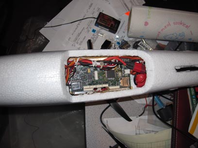
Now we can install the autopilot. First we need to run the supplied servo Y connector from the wing area down to our autopilot bay through the pre-existing hole. Next we screw the autopilot onto the rails installed in an ealier step. Make sure the air speed sensor ports are facing forward. Also make sure the GPS cable and servo Y cable are routed underneath the autopilot and out the front and rear edges respectivly so they can be plugged into the autopilot. Once that's done you can plug the receiver servo cables into the appropriate connectors on the autopilot (refure to the autopilot instruction) as well as the cables running to the servos and speed controller. Finally plug the output power connector from the autopilot into the speed controller battery input. Once again I tied everything up with some lacing material to keep it neat and tidy. I've opted to keep the speed controller tucked into the cavity aft of the autopilot. I've had no issues with overheating, but the more cautious of you may want to install it in more direct airflow.
|
 |
 |
Telemetry Radio (Xbee):
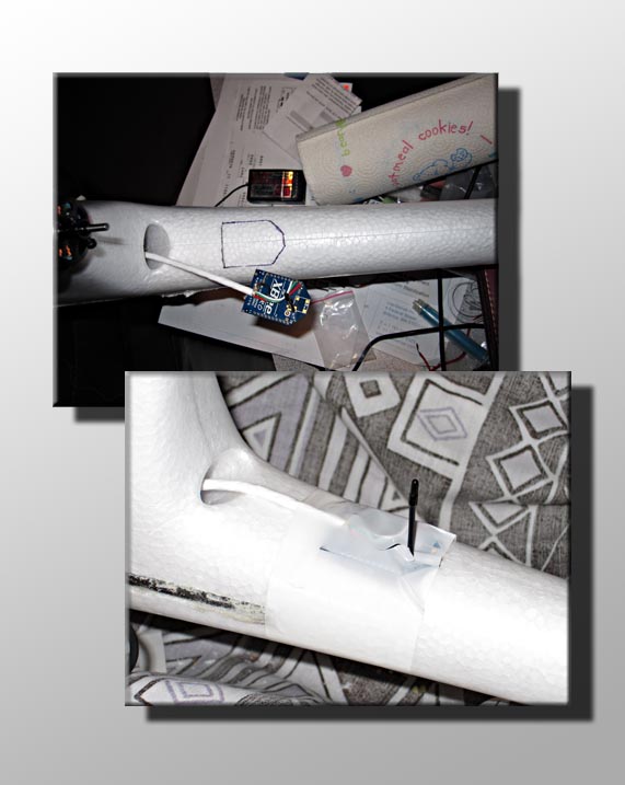
Next up is the telemetry radio. I've been using a 2.4Ghz Xbee module that has been working well for me out to 400m or so. It may work further, but that's as far as I've tested. I've placed it behind the motor on the tail boom and ran the cable trough the vent hole that leads right into the lower bay we made for the autopilot. Simply trace an outline of the radio onto the boom then using a knife cut a flat area on the boom for the radio to sit. I then put a piece of white packing tape over the top to hold the radio on securly. Last but not least is to plug the radio into the autopilot board.
|